Throwing Something Together
Being a farmer's kid, I grew up around machinery and always enjoyed building things, but I never had access to much more than a welder (stick only), a drill press, and basic hand tools. When I was in college, I managed to get a job in the Aerospace and Mechanical College of Engineering's machine shop, and this really gave me an opportunity to scratch my "makers" itch. When I graduated from college, I wanted to be able to keep tinkering around with machining, and so I purchased a Seig 8x12 Mini Lathe. I slowly worked to convert it to CNC and while the machine was decent given the low cost, it wasn't suitable for much more than cutting aluminum and softer materials, and I always wanted to be able to take deeper cuts and to Easily cut steel.
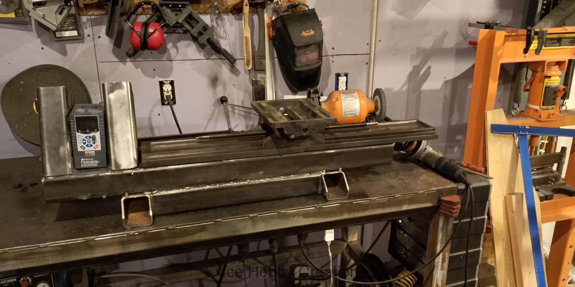
Well, eventually I stumbled across a youtube channel called RatherBWelding, run by a young man named Chris. He had a playlist where he was building a manual lathe out of a section of I beam with little more than hand tools and a welder! Despite the fairly primitive methods he was using, he actually managed to complete the project! On top of that, he was using it to make several parts for lots of other project (I really recommend you to check it out here)! Well, Chris's success and all of the different components I had acquired through the years prompted me to take a stab at building a simple manual lathe with the idea to use an old XY table (or two) for the primary axes. With little more than a general plan, I started laying out some 3" square steel tube to get a sense of scale.
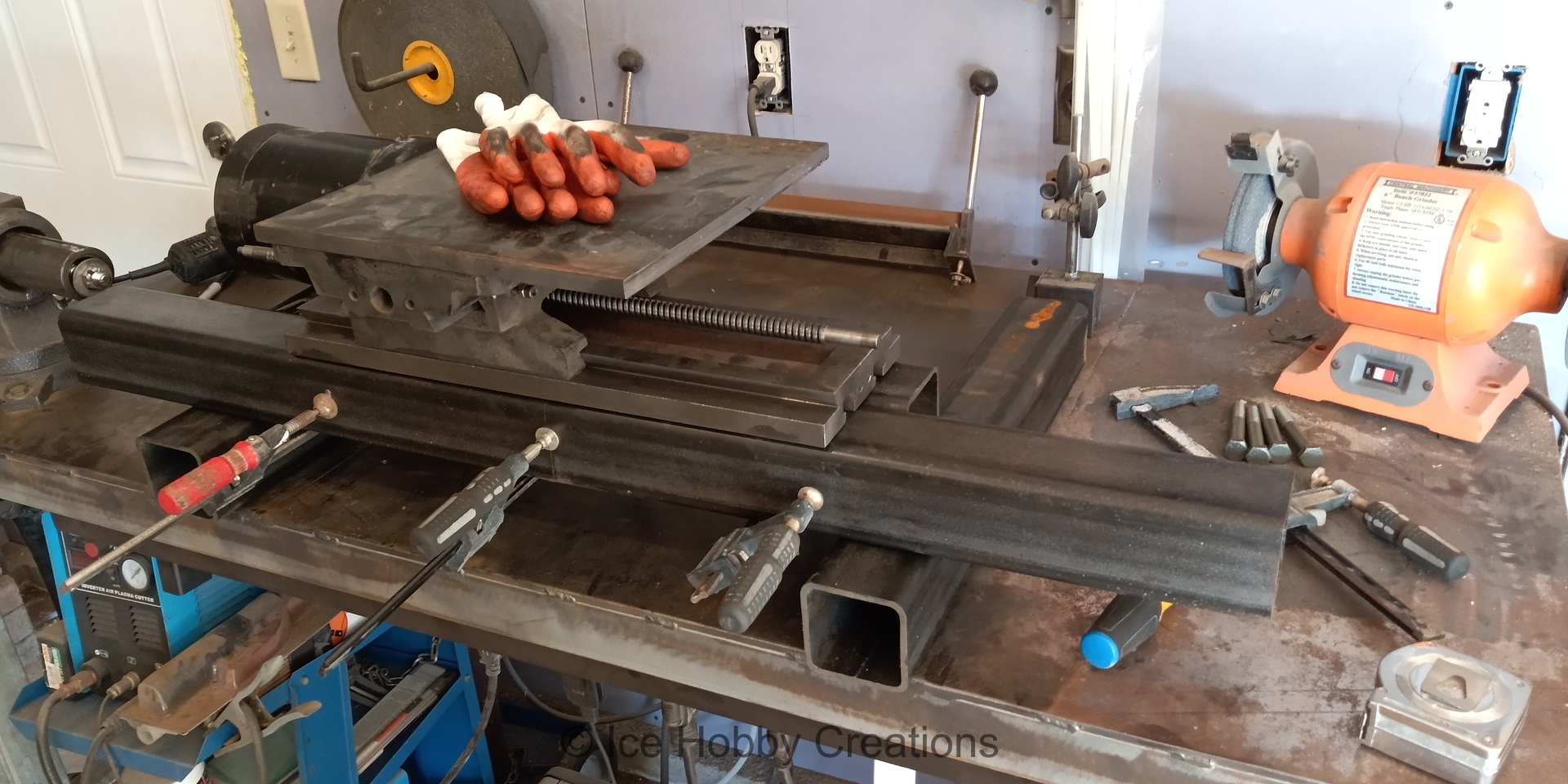
Satisfied with the general layout and capacity, I started welding!
Without a definitive plan in place, the project kind of turned into a "that seems like a good idea" extravaganza... And as a result, there were several decisions that would prove to cause headaches later on...


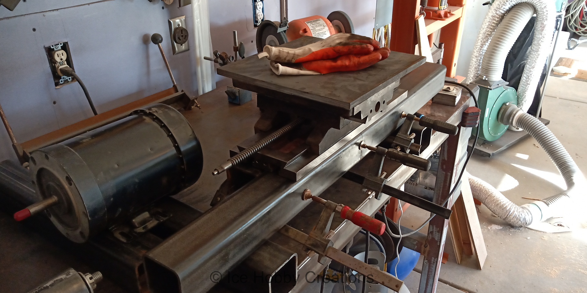
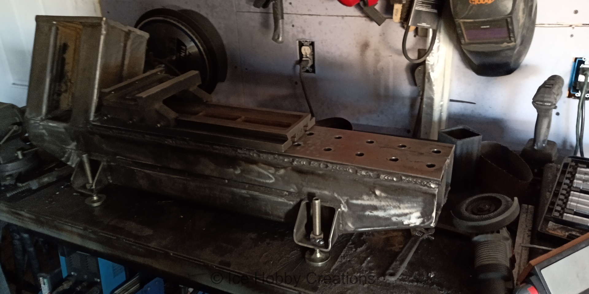
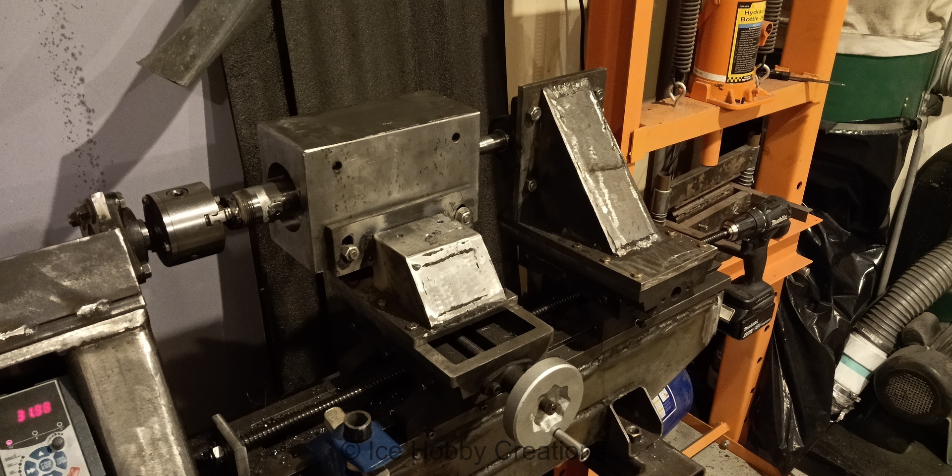
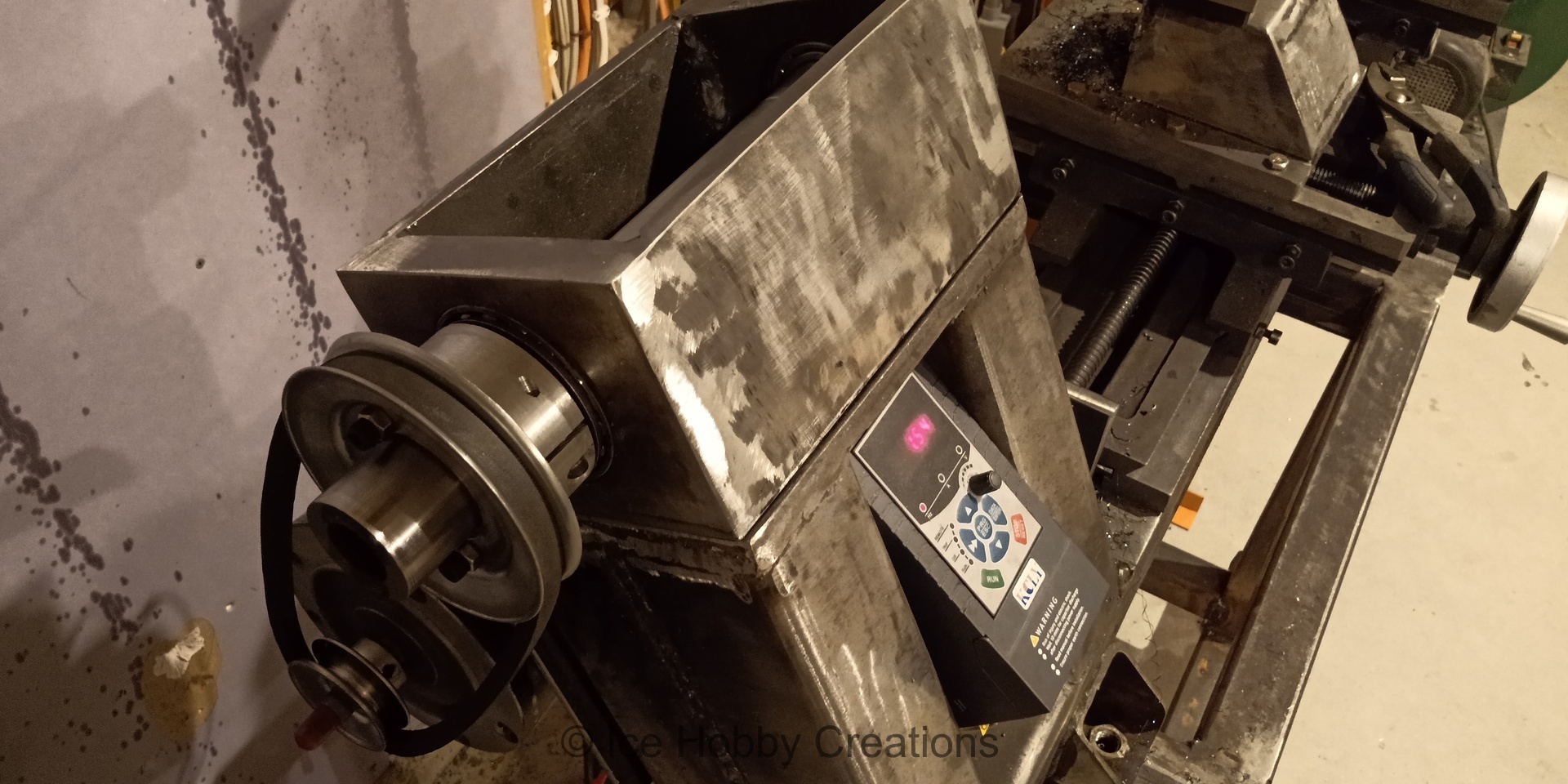
Here I've started making a temporary headstock and mounting the 1.5Hp 3ph motor. The plan was to use pillow block bearings from Northern Tool to later bore out the final headstock that would house heavy duty taper roller bearings and turn the actual spindle. I chose to use axle bearings from Northern Tool as they were decently priced, and I didn't want to invest in expensive bearings for a project that may prove worthless!
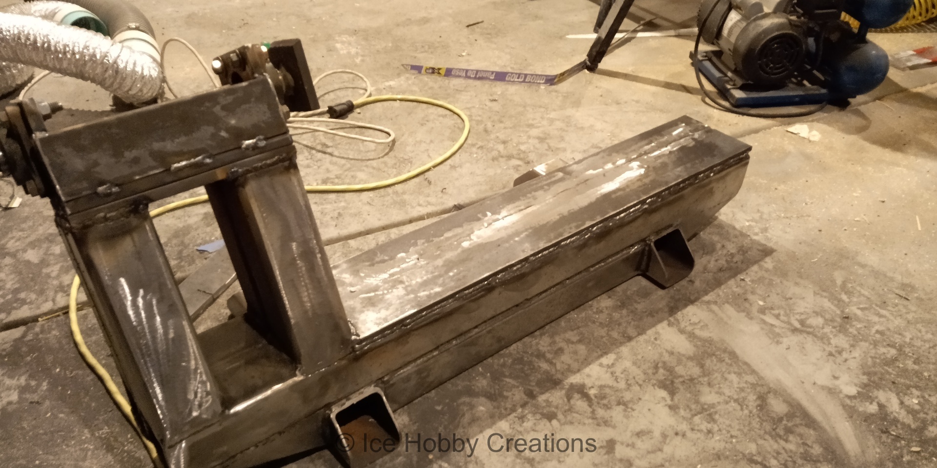

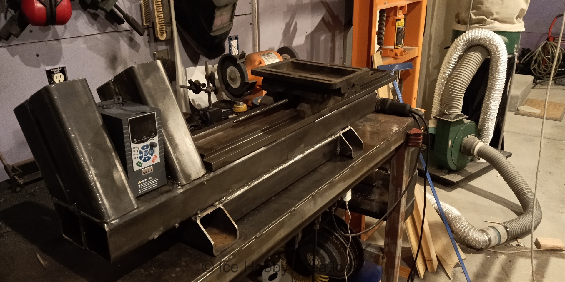
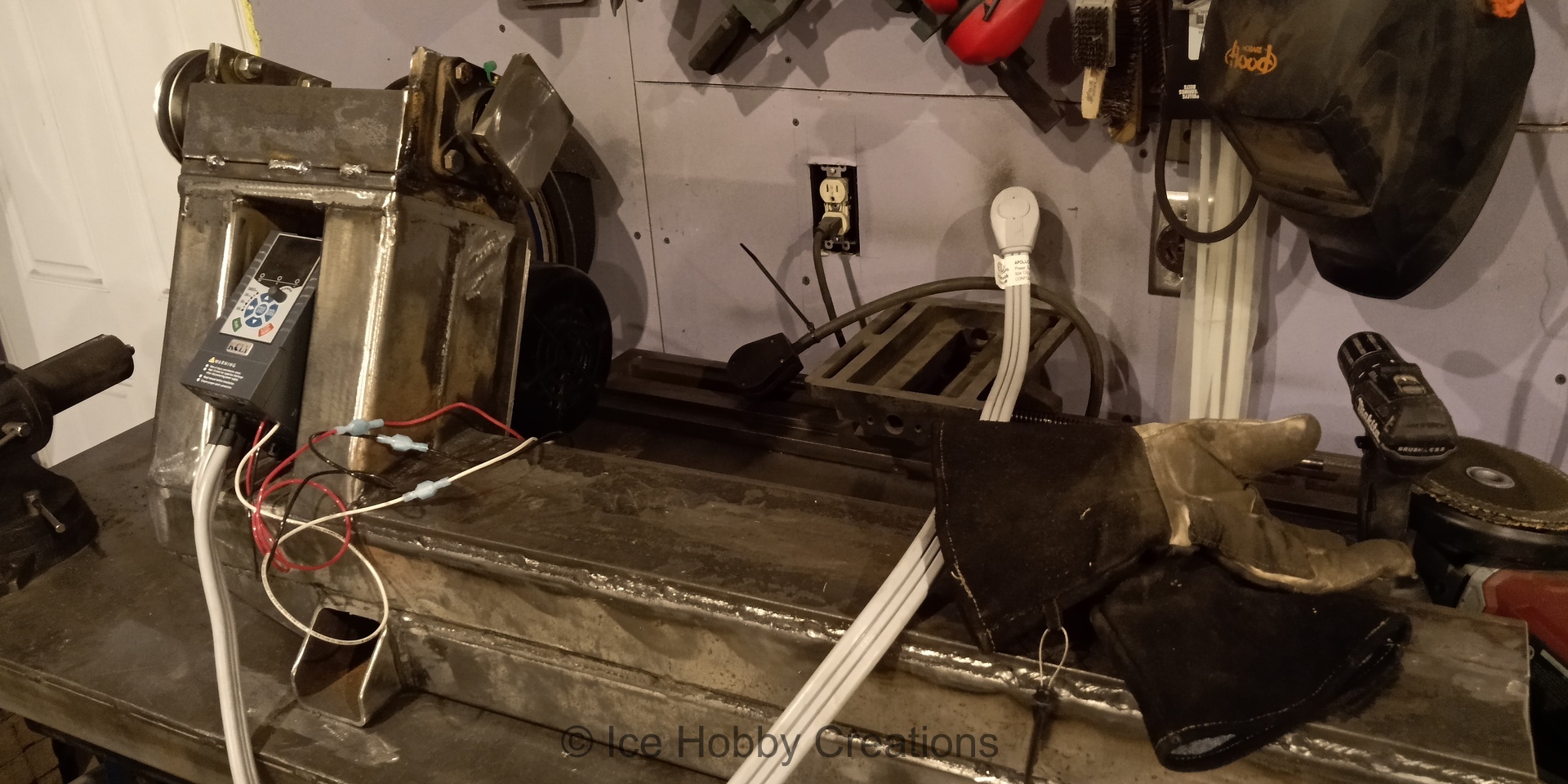
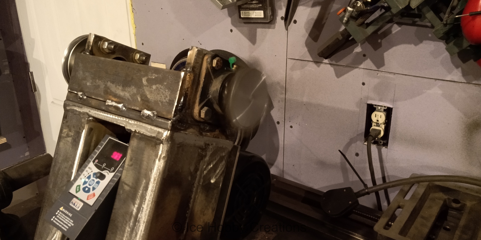
Here I've hooked up the VFD (a cheap unit from Ebay) and am ready to test the temporary spindle.
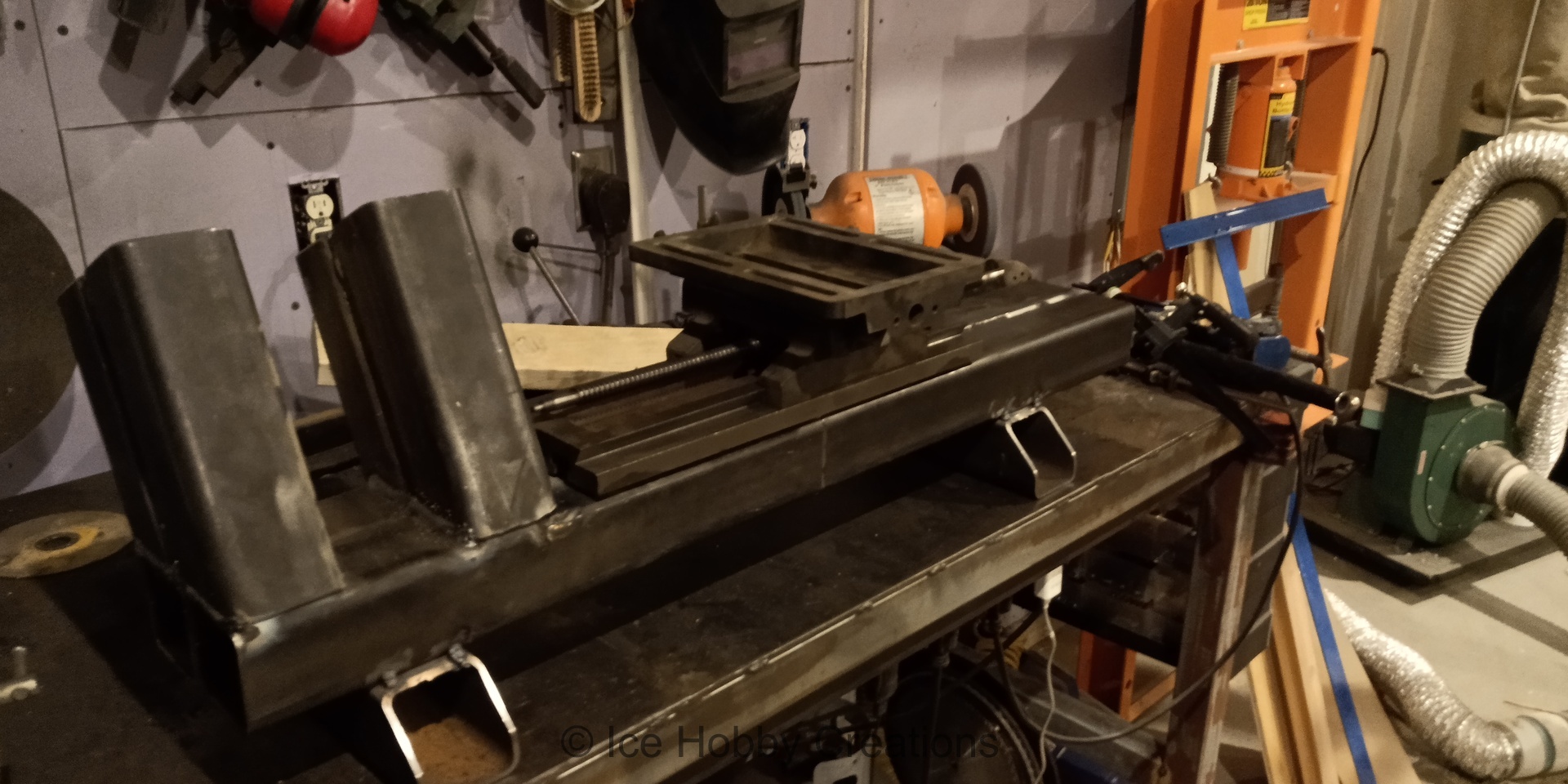
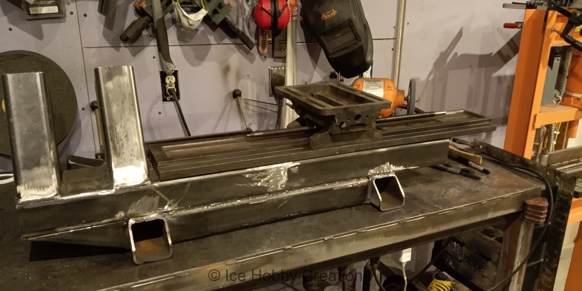
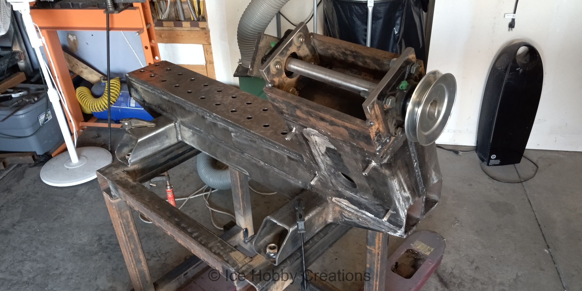
Remember how I said there wasn't a definitive plan? Well, I decided this was how I wanted to mount the XY table to the lathe bed, by using all-thread passing through the base. I also wanted to fill the machine base with concrete for added mass and damping, so this meant I needed to weld in tubes to block the concrete where the all-thread would be... In my head it all sounded like a great idea, and in fairness, it did work. However, in hindsight I regret the decision, because I wound up going a Drastically different direction with the machine and all of the holes and tubes gave me nothing but headaches later on!
What's not visible in the images is the countless hours I spent grinding on the bed to get it flat for the XY tables. All of the welding that I did wound up warping the base a decent amount so I had to grind a Lot off of the 1/2" bar I had welded to the top of the tubes. Once I got it close by according to a 4ft box level, it was time to "scrape" in the top, well, except I didn't really have the patience (or the carbide scraper) to do this "properly", so I redneck engineered a method to make everything a bit flatter than it currently was: I spotted the surface with my surface plate (a 12x18" unit from Shars) and then hit the high spots with my angle grinder, after all, it just needed to provide adequate bearing surface for the top of the flat (hopefully) XY Tables.

Imagine my surprise when I finally discovered that the top of the XY tables (bought probably years apart, but both from Shars) was not a consistent thickness? Thankfully the actual dovetail dimensions were the same (or close enough for what I was going to accomplish!) so I just had to put shim stock under the section of table furthest from the chuck (are you convinced of how poorly planned this project was!). Also, note the completely Not-janky tool-post setup!

I Think this was one of the first things I ever turned on the machine, and I think it was going to be used for the tailstock (possibly), but it's more likely that I just got to a point where I though I could "turn" something and so I grabbed the first bit of steel I could find and had a go of it!
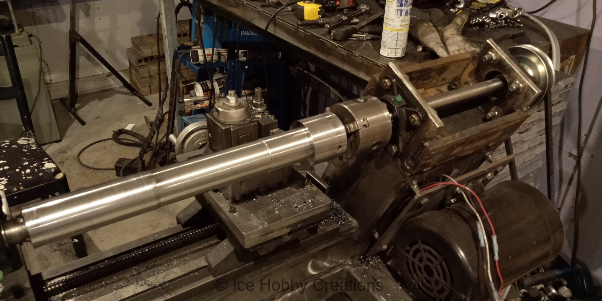
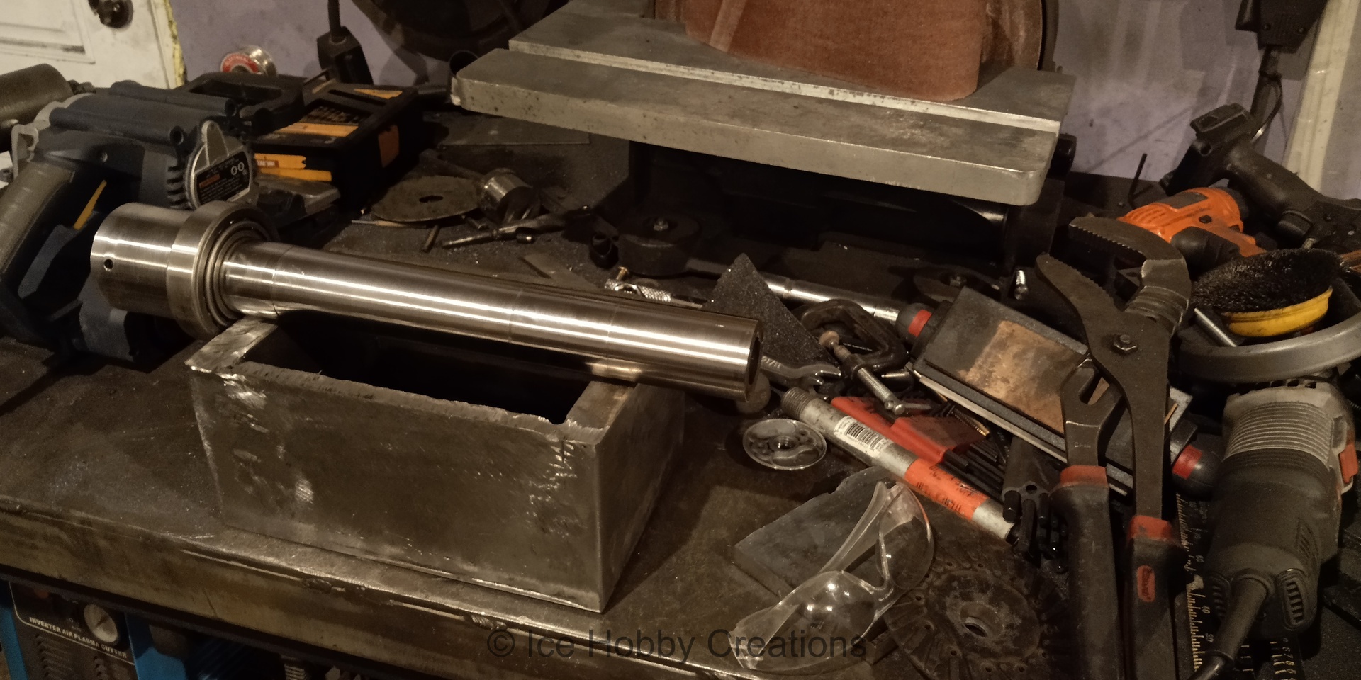
Never one to wait until the tools are actually Ready to be used, and high on the success of machining the temporary spindle to mount my old mini lathe's 3-jaw chuck, I cludged together a setup to see what I could Really (really?) do with the machine. If it hadn't been (somewhat) successful, I would be way more ashamed of this setup than I actually am. Here I have a temporary headstock with pretty awful bearings, a temporary tailstock (also with pretty awful bearings), and a temporary means of running the carriage, oh and with a slightly Less temporary tool-post setup... What could possibly go wrong... or right for that matter!
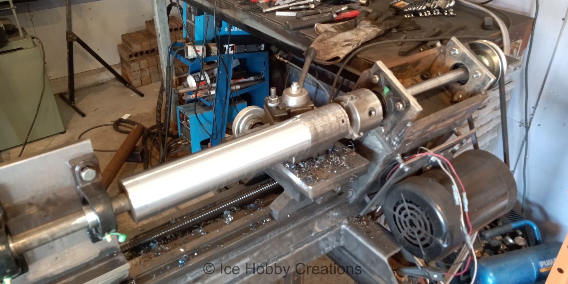

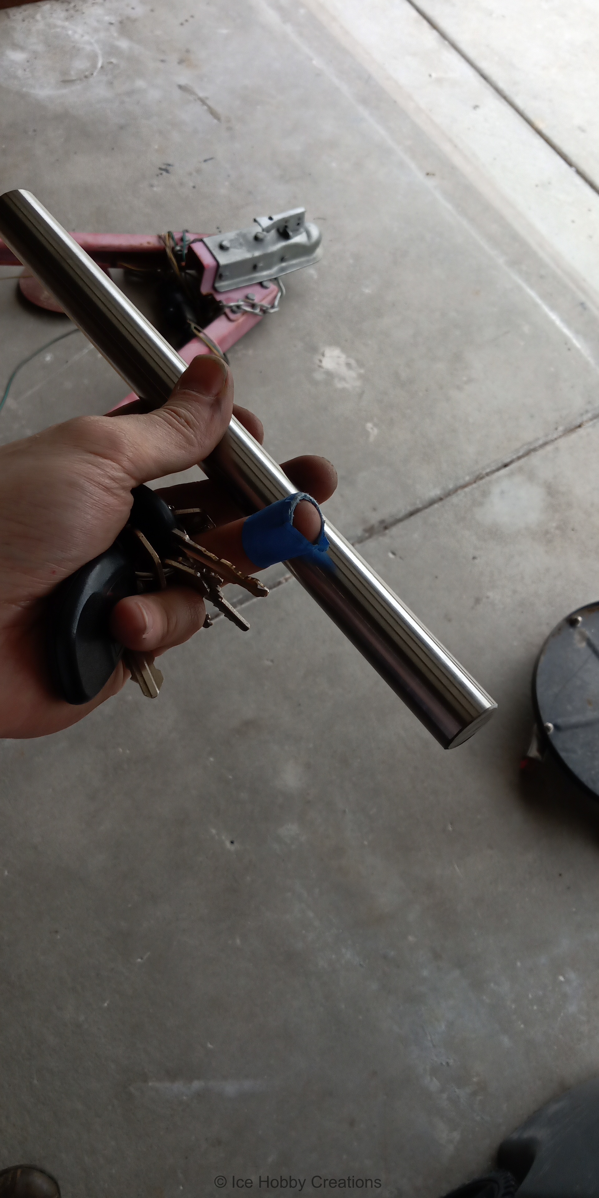
There is something cathartic about seeing dull material become shiny as it is slowly transformed into a Real, totally legitimate, never to be replaced or upgraded ever again, part! Here is the actual spindle taking shape. Now, you are probably thinking, how accurate can Anything being turned on this be? Well, that's a perfectly fair question, haha. I mean, it's pretty much guaranteed the Z axis is not parallel to the spindle axis, right? This thing must produce Huge tapers over the ~18" length I'm turning here! Well, to counteract that, I turned the middle portion down a bit smaller than the bearing ID so I only had to tune where the bearing seats were locally. Then, I could get it close and bring it in better with sandpaper. Ultimately, I managed to get both bearing seat locations to be a nice transition to press fit (As measured when I forced the bearing races on, haha).

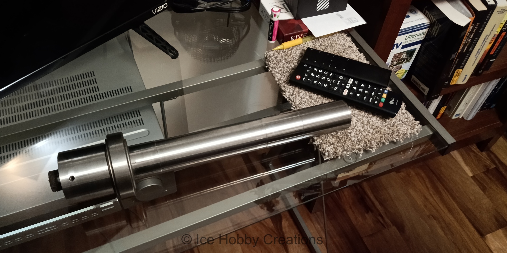
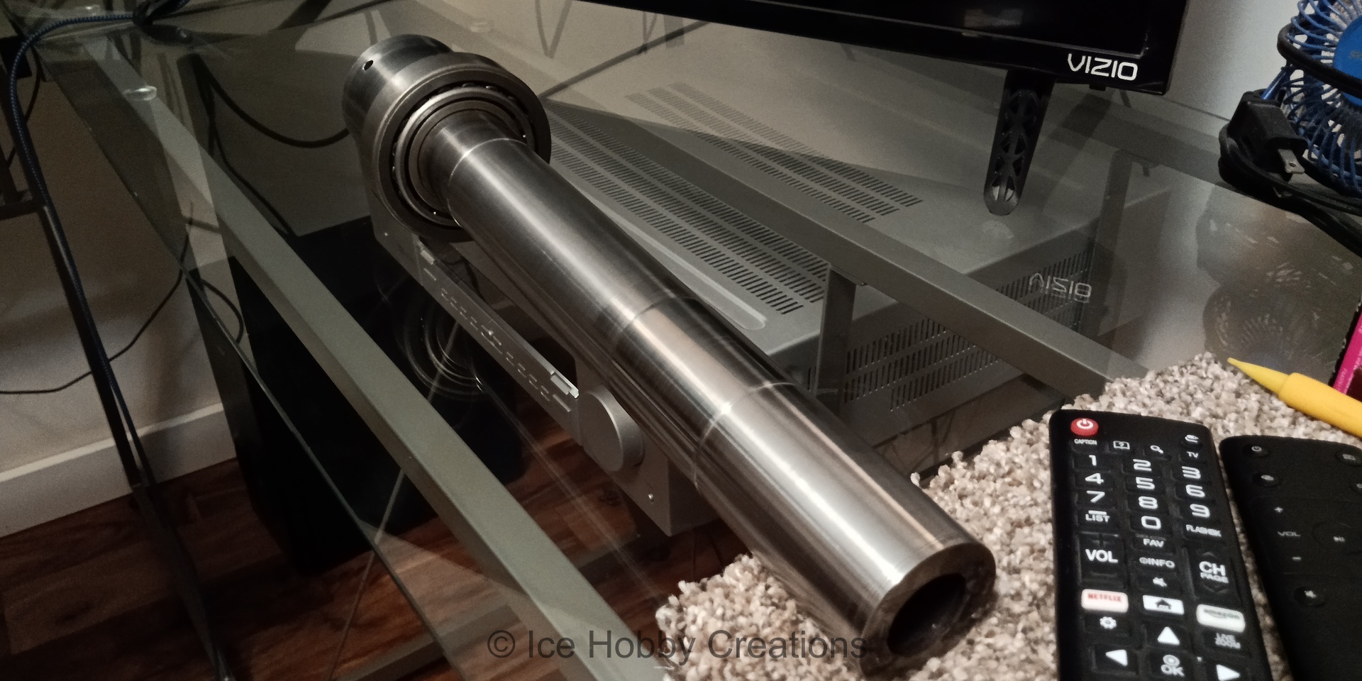
Real machinists (hobbyist or professionals alike) are probably wondering what's so special about a likely out of round shaft, but I think it's pretty impressive what can be accomplished with pretty basic tools and parts! Shiny...
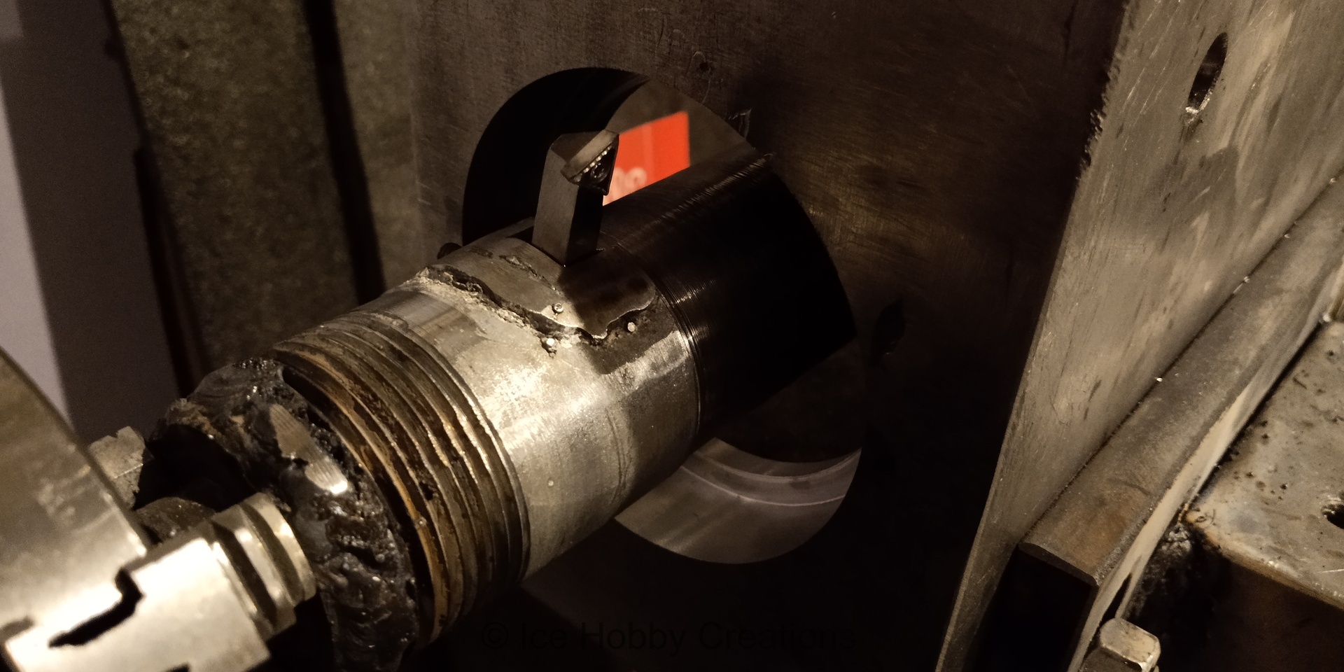
Here I'm figuring out my plan of action to bore out the final headstock block. If you thought sketchy setups were finally over, you'd be wrong. Here I have pre-drilled the bearing seats using a hole-saw. I've also ground the bottom of the headstock flat (or as flat as I had the patience to get it) and have lined it up with the Z-axis with a dial indicator. The tailstock has also been adjusted to try and minimize mis-alignment of the boring shaft with the Z-axis.
And what Beauty of a boring bar it is /sarcasm. Cludged together from the largest diameter plumbing pipe available from Lowes, I welded (can you call what you are seeing weld?) a cap and boss with a small hole at one end to be held in the 3-jaw chuck. The other end also had a cap and boss with small hole to fit over the "live center" in the still temporary tailstock. 1/4" carbide insert tooling from, you guessed it, Harbor Freight was used (just because I could pick it up locally). As you can imagine, boring the remainder of the bearing seats was quite tedious, as to check the diameter, the tailstock and boring bar had to be removed completely to get enough access.
At the end of it all, I wound up with a great fit on one bearing and a slightly oversized seat on the other. Instead of starting over and trying again, I decided to just "peen" the edge of the bearing seat slightly to "firm" up the fit. By now, I was already thinking how the "finished" machine would upgrade its own parts, lol!
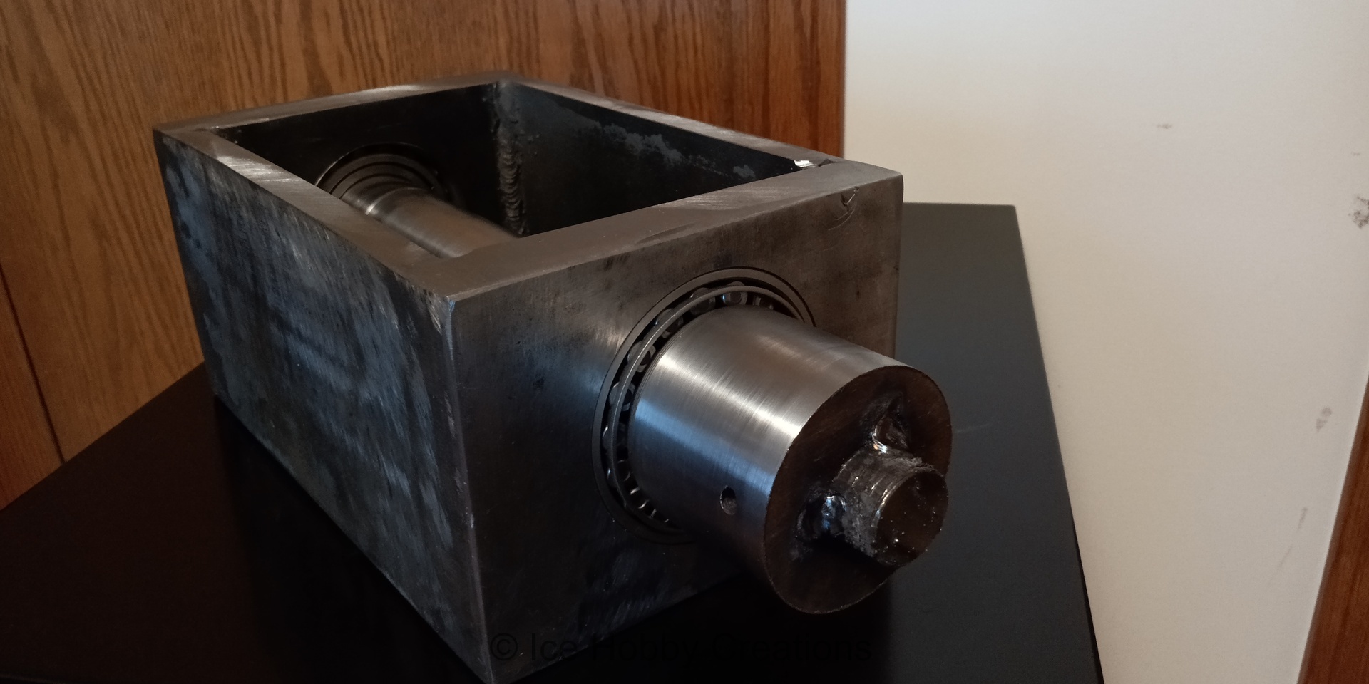
Excited to try out the new spindle and housing (as the novelty of being able to turn bigger material was wearing off, the quality of certain temporary components was starting to annoy me!), I bored out a hunk of aluminum I had cast into a cylinder years ago, put a slit in it so I could clamp it down on the end of the spindle, and put a couple of holes to mount a pulley. At this point, I had completely convinced myself this was another "temporary" headstock, and therefore shortcuts were justified! I mean, I hadn't even planned in a good seal solution (are you starting to question if I'm really an engineer or not?)...

With all of my shortcuts justified in my mind, I could weld a plate (sigh, why didn't I do that before I started turning the spindle???) to the end of the spindle to give me enough meat to machine in a decent register for chucks and backplates. With angular contact bearings and the ability to put a decent preload on the spindle, I was excited to see what I could do! I don't have documentation of it, but I remember being sorely disappointed with the results of all of my effort! Had all of my concessions and shortcuts come to bite me? Turns out I hadn't gotten a decent preload on the AC bearings after all /facepalm. Shiny...


The small 3-jaw chuck just wasn't sufficient, so Amazon sent me a cheap 6" 3-jaw chuck and I set out to make a backplate for it. Also, probably going to regret not putting something up to protect my drywall from oil as I'm cutting stuff...


If you are wondering why this project is called Cnc Lathe, well just head on over to the next page.